How to Build a DIY STM32 Oscilloscope (Step-by-Step Guide)
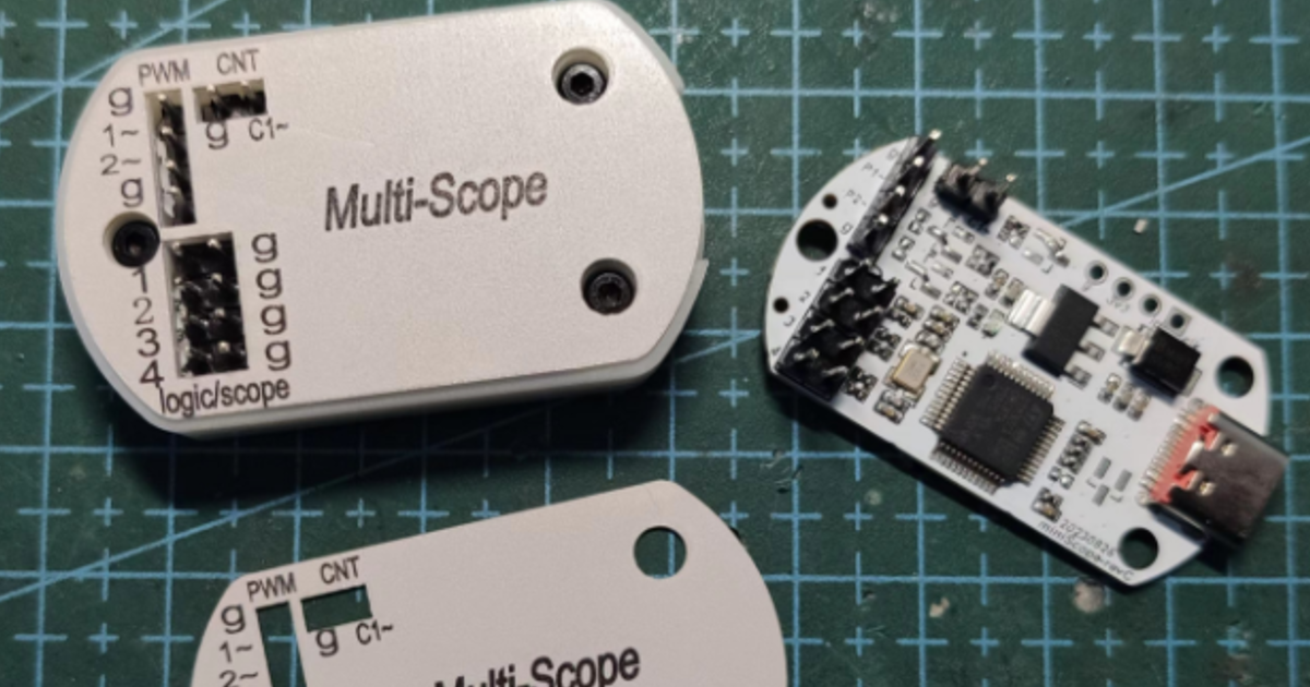
A Compact STM32-Based Multifunction Instrument (Oscilloscope + Logic Analyzer + More)
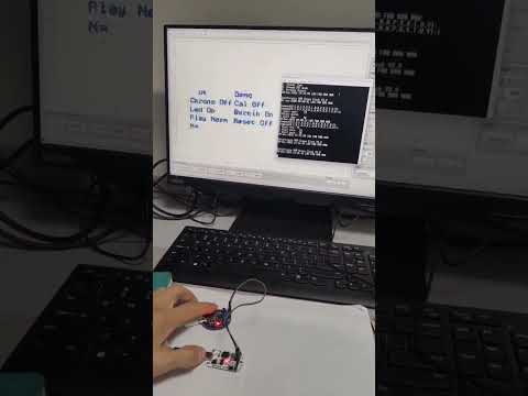
🎥 PCBA and 3D printed case:
There is a very popular multifunction oscilloscope project on GitHub that uses an STM32 development board. With just a few Dupont wires and a USB cable, it can be turned into a versatile instrument featuring:
- Oscilloscope
- Logic analyzer
- Voltmeter
- Counter
- PWM signal generator
The project also provides a Qt-based desktop application that supports Windows, Linux, and macOS, making it truly cross-platform.
🔗 Original project:
🚀 My Hardware Implementation
🔗 Project repository:
To improve usability, I designed a dedicated hardware version of this project.
Motivation
While the original project is powerful, it has one major limitation:
It is designed only for generic development boards and lacks dedicated hardware.
This significantly affects usability and limits its broader adoption.
To address this, I designed a custom hardware solution, including:
- A dedicated PCB
- A compact 3D-printed enclosure
- Custom silkscreen labeling
Hardware Design
The design is based on the widely used STM32F103C8T6, which is also used in my integrated SimpleFOC project.
The firmware implementation is relatively straightforward, mainly leveraging:
- ADC (for voltage sampling)
- Timer peripherals (for signal generation and measurement)
- GPIO (for logic analysis and control)
Pin Mapping
Following the original Blue Pill (STM32F103C8T6) design:
| Function | Pins |
|---|---|
| Oscilloscope / Voltmeter | PA1, PA2, PA3 |
| Logic Analyzer | PA1, PA2, PA3 |
| Counter | PA8 |
| PWM Generator | PA15, PB6 |
Schematic Design
The schematic is built around a minimal STM32F103C8T6 system, with all required pins broken out for easy access.
PCB Design
TOP
BOTTOM
Given the simplicity of the circuit, a 2-layer PCB is sufficient.
- 📏 Size: 42 mm × 22 mm
- Compact and enclosure-friendly
3D PCBA
A full 3D model of the assembled PCB was created to verify mechanical compatibility with the enclosure.
IBOM (Interactive BOM)
An interactive BOM was generated to simplify assembly and component identification.
Enclosure & Silkscreen
The enclosure and silkscreen graphics were designed using JLCEDA:
- Custom-fit enclosure
- Clear interface labeling
- Much better usability than bare development boards
Usage
The device connects directly to a PC via a USB Type-C cable.
Steps
- Connect the device to your computer
- Launch the desktop application
- Select the corresponding serial port
- Start using the instrument
The UI is intuitive and easy to understand.
Software
The desktop application is built with Qt, offering:
- Cross-platform support
- Real-time waveform display
- Easy interaction with all functions
Resources
All files are available in the GitHub repository:
- Gerber files
- Pick-and-place files
- BOM
- 3D enclosure files
- Silkscreen files
🔗 Repository:
BI4WMS Scope Hardware
Conclusion
This project transforms a development-board-based tool into a compact, integrated, and user-friendly multifunction instrument.
It demonstrates how open-source projects can be extended with custom hardware to significantly improve real-world usability.
⭐ If you find this project useful, feel free to star the repository or contribute!