SimpleFOC Integrated Board from Zero to One - Part 3
SimpleFOC Integrated Board Hardware Practice: From Zero to One (3) – Power-Up and SimpleFOC Software Setup Guide
BI4WMS FOC Driver Board - Power-Up and SimpleFOC Software Setup Guide
Board Preparation
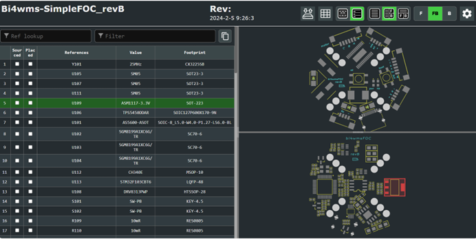
Solder the components onto the PCB according to the IBOM (Interactive Bill of Materials).
Key components should be soldered first.
Use a multimeter to check the power rails for any short circuits. Once there is no short circuit detected, power the board using a regulated DC power supply with current limiting enabled. Measure the 3.3V output.
If the 3.3V output is normal and the power indicator LED lights up, it indicates that the basic power-up functionality of the circuit board is working correctly. Next, we will prepare the software environment.
SimpleFOC Software Debugging Environment Setup
1. Install Arduino IDE
Download and install the Arduino IDE from the official website. The classic 1.8.x version is recommended.
2. Configure STM32 Support in Arduino IDE
2.1 Add STM32 Core
Go to File → Preferences, and in the Additional Boards Manager URLs field, add the following link: https://github.com/stm32duino/BoardManagerFiles/raw/main/package_stmicroelectronics_index.json
2.2 Install STM32 Boards
Go to Tools → Board → Boards Manager, search for STM32, and install the STM32 series development board package.
2.3 Install STM32CubeProgrammer
Download STM32CubeProgrammer from the official ST website and install it with the default settings.
2.4 Test STM32 Arduino Configuration
Open any STM32 example sketch in the Arduino IDE.
Press and hold the BOOT0 button on the driver board, then connect the Type-C cable to power on the board (this enters bootloader mode).
Compile and upload the sketch directly from the Arduino IDE.
Note: The hardware design utilizes the STM32 built-in bootloader with UART download functionality. Since the board has an integrated USB-to-UART chip, firmware can be flashed using only a single Type-C cable.
You can also generate the binary file after compilation and upload it using STM32CubeProgrammer in UART (serial) mode. If the upload completes successfully, it confirms that the board’s programming function is working normally.
3. Install SimpleFOC Library
Install the library using Arduino IDE’s Library Manager:
- Go to Sketch → Include Library → Manage Libraries
- Search for SimpleFOC
- Install the SimpleFOC library
4. Test the BI4WMS FOC Driver Kit
Use the official test code from the SimpleFOC library. If it compiles successfully, the library has been installed correctly.
Example codes can be found in the Arduino IDE under:
File → Examples → SimpleFOC
5. Board Testing
Use the bluepill_position_control example. Modify the magnetic sensor and DRV8313 driver configurations according to your hardware. The example can be downloaded directly from GitHub.
https://raw.githubusercontent.com/bi4wms/SimpleFOC/refs/heads/main/bi4wmsFOC.ino
- Press and hold the BOOT0 button, then connect the Type-C cable to power the board.
- Compile and upload the firmware.
- Supply 12V power to the motor.
- Once initialization is complete, open the Serial Monitor and send commands to control the motor.
For a complete list of interaction commands and detailed usage instructions, please refer to the official SimpleFOC documentation.
Next Article: We will analyze and explain the specific SimpleFOC example code in detail.